E type Dashes THICK. F type Dashes THIN.
Sectional Views In Engineering Technical Drawings
A simple bracket is shown in Fig.

. Partial or Broken Out Section 4. Phantom line type Dr. Types of Sectional Views Full Section.
K half section The view Obtained When the cutting plane goes half way across the Object to the centre line. You can create one or more base views on a drawing sheet. - इजनयरग डरइग म सकशन क परकर 1.
D type Continuous THIN Zig-Zag. This Mechanical Drawing Tutorial presents a sectional view showing inner details by an imaginary cutting away of part of the object. What is Full Section.
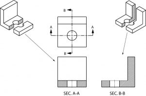
Section view is shown outside the view. When specific features of an object that need highlighting are not located. 81 and it is required to draw three sectional viewsAssume that you had a bracket and cut it with a hacksaw along the line marked B-B.
Half sections or views. The first view created in a drawing. A type Continuos Thick.
K half section The view Obtained When the cutting plane goes half way across the Object to the centre line. Full section The view obtained even the cutting plane is right across the object. What are the different types of lines used in engineering drawing.
Haitem Hichri Lines Used in Section Views Cutting Plane Line. B type Continuous THIN. A cutting plane does not necessarily need to cut the whole object.
The default orientations are based on the origin in the digital prototype. There are three major types of sections used in engineering drawing. This is the most common section called a full section with the imaginary laser cutting a line across.
A revolving view is effective for elongated objects or. In both cases the object should be standing on its base when the. A section is used to show the detail of a component or an assembly on a particular plane which is known as the cutting plane.
You select the orientation of the view when you create it. Used to show where the object is being cut. Types of Section in Engineering Drawing.
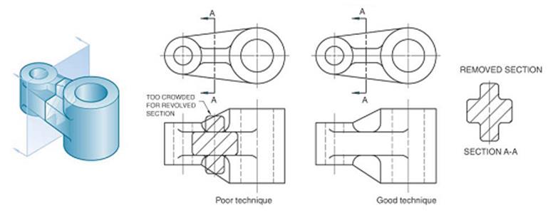
REVOLVED SECTION VIEW Basic concept 15. Engineering Working Drawings Basics Page 8 of 22 parallel to the object surface. The base view is the source for subsequent views and controls the scale and alignment for them.
C type Continuous THIN Freehand. A full section is the most widely-used sectional view. Sectional Views in AutoCAD R Greenlee Page 1 Chapter 5 Sectional Views There are a number of different types of sectional views that can be drawn.
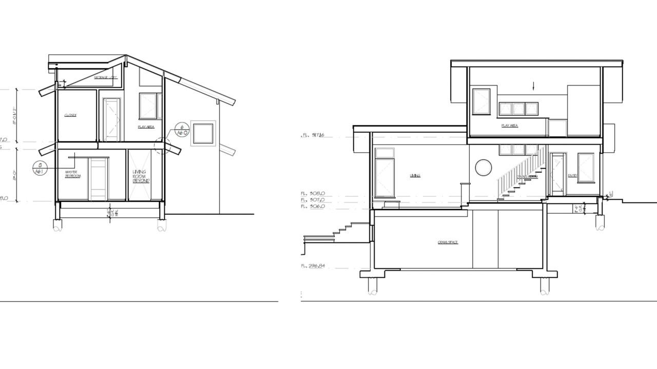
EvaluateManufacture a Final Product Activity Types of Engineering Drawings Top view Side elevation Hand-drawn engineering drawing of a bench Traditional blueprint of building design Exploded view drawing of bathroom exhaust fan Student CAD drawings Modern CAD drawings. Engineering drawings are often referred to as Blueprints. An elevation drawing is a view taken from a point outside the object without any slicing.
Superimposed to orthographic view. All the vertical lines stay vertical compared to front view and otherwise. In this type of section only half of the space or object is cut away.
Material has been cut in a sectional view. In both cases the object should be standing on its base when the. Break from orthographic view.
A section drawing is a view taken after you slice an object then look at the surface created by the slicing. FIGURE PART OR LOCAL SECTIONS Part at a to detail of type u normal the maln m drawings in this THE FULL SECTIONAL VIEW the d FIGURE 310. Basic Components of an Engineering Drawing.
There are three major types of sections used in engineering drawing. However the terms are becoming an anachronism since most copies of engineering drawings that were made using a chemical-printing process that yielded graphics on blue-coloured paper. If two or more parts are included within the same sectional view each part must have.
Section lines are evenly spaced at any inclined angle that is not parallel to any existing edge line and should be visually distinct from the continuous lines that define the boundary of the sectional view. What is Half Section. Detail Views A detail view is a separate large-scale drawing view of a small section of another view.
Types of Views in Engineering Drawing. REMOVED SECTION VIEW Removed section is revolved section. REVOLVED SECTION VIEW Basic concept 16.
Broken crosshatching shows where cutting plane line intersections material each material has its own crosshatching cutting plane line shows where the imaginery knife cuts thru the part line is always parallel to a line of rotation shows which cutting plane line. 6 Types of sectional views Full sections. REVOLVED SECTION VIEW Placement of revolved section 1.
Section views types of section views 1. The cutting-plane line cuts halfway through the part and removes one quarter of the material. A cutting plane line shows where object was cut to obtain the section view.
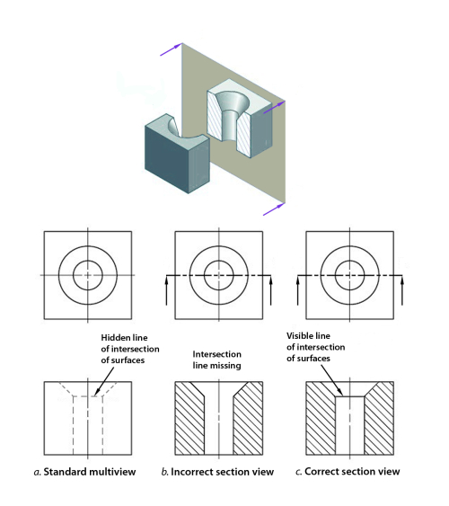
In this view the cutting plane is assumed to bend at a right angle and cuts through only half of the. Isometric drawings show parts as three-dimensional. You have learned that when making a multiview sketch hidden edges and surfaces are usually shown with hidden dash lines.
Sectional views in engineering technical drawings Half Sectional views. Includes an explanation. Engineering drawing views engineering drawing types INTRODUCTION.
A few of the more common ones are. Therefore any surface that is not in line with the three major axis needs its own projection plane to show the features correctly. Half Section is used to the exterior and interior of the part in the same view.
Following are the different types of lines used in engineering drawing. Half sections are commonly used to show both the internal and outside view of symmetrical objects. Haitem Hichri Lines Used in Section Views Section Lines Shows where hatch the part is being cut.
DISPLACEMENT OF HOLES IN SECTION ciralar in out-ting at pitch from in raffer 32 Drawing sectional views In orthogonal to complete of an ng Intemally of a The of C line to Nhlch it The of a lire type A. Full sections half sections broken sections rotated or revolved sections removed sections offset sections and assembly sections. G type Chain Thin.
The line that separates the different types interior and exterior may be a. 6 types of engineering drawings 1. Types of Engineering Drawings Design Step 6.

Sectioning Technique Engineering Design Mcgill University
What Is A Sectional View 6 Types Of Sectional Views
2

Sectional Views

01 Cad Makingthat
Sectional Views Basic Blueprint Reading
Engineering Drawings
Sectioning Technique Engineering Design Mcgill University
0 comments
Post a Comment